- UID
- 468
- UCC
-
- 声望
-
- 好评
-
- 贡献
-
- 最后登录
- 1970-1-1
|
转载自xwiki
现在有许多介绍X3自制飞船模型的文章。
在常见的有:
- 简单应用X3材质贴图贴到人家做好的模型上面。
- 修改现有的X3模型,并用X3材质贴图。
- 用之前别人做的模型建立自己的模型。(就象描写一样)
- 从零开始做一个模型。1.
注意: ...这里作者说了些做人要厚道的道理...(省略了)
下面列出了将要用到的4个软件:
3ds Max 8 by Autodesk
Polygon Cruncher 7 by Mootools
DBOX2 by doubleshadow
X2BC by doubleshadow
注意:你也能使用gmax替代3ds Max。 技术上来看gmax就是3ds Max 4. 同时, 除非以别的方式指定的, 我通常使用Editable Polygons。
当然, 最终是你选择使用Editable Polygons还是Editable mesh等等...
在建一艘船之前,我们需要知道大概的模样。 如果你本身就是个模型爱好者,那会做出一个高度详细的造船计划......或者如果你像我, 那就这样:
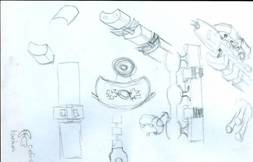
以下整个"造船过程"暂时不翻译,因为一来我们要做自己的船,二来每人用3DsMax方法不同,且下文图片也很多了. By HammerSun
Step 1 – Build the Front Section of the Ship OK, the first step is to create the mesh for the front section of the ship. Because I want nice swoopy lines and curves, I'll be using Splines and the Surface modifier.
- Fire up 3ds Max, or if it is already running select File->New, tick New All, and OK
- Go to the Create panel, select Shapes, and click on Line.
- You will want to set the Drag Type on the Creation Method rollout to Smooth.
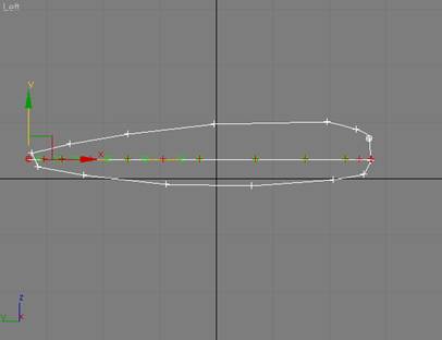
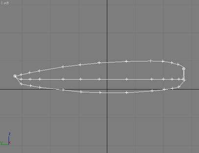
- Make the Left viewport your current focus, and draw the profile of the front section of your ship.
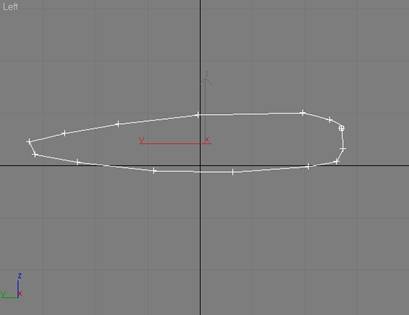 - Right-click on the spline, select Properties, and on the General panel of the Display Properties pop-up, turn on Vertex Ticks.
- Right-click again on the spline, and select Convert to->Convert to Editable Spline.
- On the Modify panel, call your spline object something imaginative - like front.
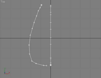
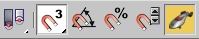
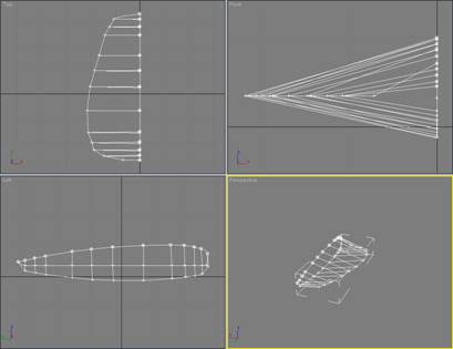
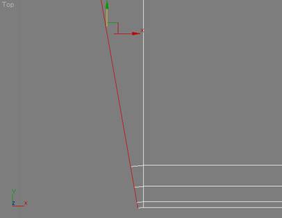
- Right-click anywhere in the top viewport to make it active, and on the Modify panel, go down to the Geometry rollout and click on Create Line.
- Then in the top viewport, draw the profile for the left ship of the front section. Don't worry too much about the shape, or connecting things at this point, as we will have plenty of opportunity to tweak things later. You should have something that looks like:
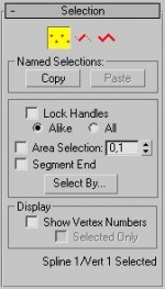
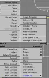
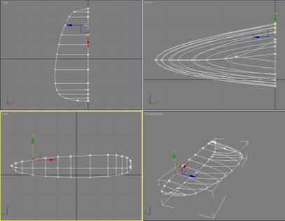
 - On the Modify panel, go to the Selection rollout and click on Vertex:
 - In the Front viewport (or Back, depending on how you set things up), select all the vertices on the left-side profile you just created, and then in the Left viewport, adjust the height for the sides of the front section. This will also be the widest point on the sides of the front section. You should now have something like:
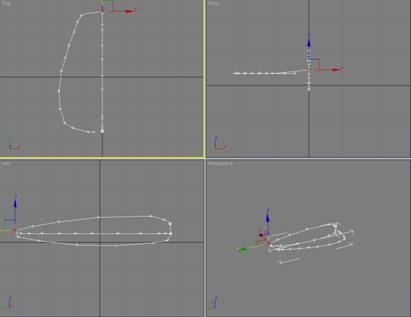
 - Up on the toolbar (at the top), turn on the 3D Snap Toggle, as shown to the right:
 - Then right-click on the 3D Snap Toggle to display the Grid & Snap Settings, and make sure that Endpoint is turned on, and that Grid Points is turned off. On the Options panel of the Settings dialog, make sure that Axis Constraints is turned off, and close the dialog box.
- With Vertex still selected on the Modify panel, drag and snap the front of the left-side profile to the tip of the first spline you created. It should look like:
 - Do the same with the back of the left-side profile.
OK, now let's start to refine the profile of the front section for our ship. (Oh, you are saving things as you go along, right?)
We are going to need to draw lines from the top of the profile, around the side, to the bottom of the profile. The lines will need to start at a vertex, go through a vertex on the side, and end at a vertex at the bottom. To do this, we will want to make sure we have the correct number of vertices, and that they are properly lined up.
- Make sure that the spline is selected, Vertex is selected on the Modify panel, and that 3D Snap is turned off.
- Now click on Refine in the Geometry rollout, and start adding vertices.
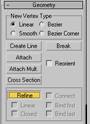 - You should only work in the Left viewport. When a vertex needs to be moved along the left-right axis, temporarily turn off Refine, move the vertex, turn Refine back on... and continue adding vertices. When you are done, the left-side view should look something like this, with all the vertices fairly well lined up:
 - Now turn the 3D Snap toggle back on, and click on Create Line on the Geometry rollout.
- Start adding vertical lines connecting each of the three vertices. When you are done, your spline should look something like this:
 - OK - now for the tricky part. Turn off 3D Snap, and select all the vertices (Ctrl-A).
- Right-click on the spline, and then select Smooth for the Corner Type.
 - At this point, you need to be a bit creative. Start selecting the individual vertices, and move them around until you have a nice smooth shape. Pay attention when selecting vertices, as they are not welded (yet), so it is important to select both vertices in a given pair by dragging a box to select them.
- Take your time, because this is the final shape that the front section of your ship will have. You should end up with something like:
 - When you are done moving things around, make sure that the spline is still selected, and that the vertex sub-object selection is turned off.
- On the Modify panel, select the Surface Modifier from the Modifier rollout list, and then turn on Flip Normals and Remove Interior Patches.
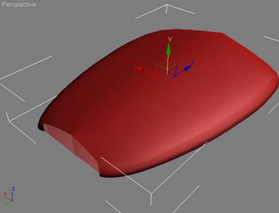
- The Perspective viewport should now show something that the following:
 - At this point, I like to covert the spline to an Editable Polygon, and apply a Mirror modifier to see what I have. I'm more concerned at this point with the basic shape. There will be way too many polygons for such a simple shape, but I will take care of those in a minute with Polygon Cruncher.
- Here is what I have so far:
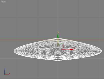
 - OK, this step is optional, but strongly recommended. The basic shape currently has 3,200 polygons... which is about twice as many as I can afford. I solve this little problem with a shareware tool called Polygon Cruncher from Mootools. After reducing the number of polygons using this tool, I now have a mesh that looks like:
[edit]
Adding detail to the Front Section The next step is to add some detail, like a bridge with windows, and maybe a small cut-out in the nose portion to locate a sensor array.
For this, I'll use the Boolean Compound Object in 3ds Max. Please note: you should be very cautious in your use of Boolean operations in 3ds Max. It can be a bit flaky depending on the underlying mesh, so it is not always something you can count on.
Let's try it.
First, the cut-out for the sensor array:
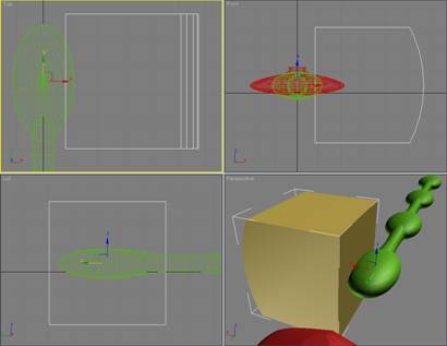
- Using Create->Geometry, select Extended Primitives from the pull-down menu, and then click on ChamferBox. On the Parameters rollout, set Width Segments to 3, Fillet Segments to 3, and leave the Length and Height Segments at 1.
- Make sure the ChamferBox is deep enough, and to add a bit of detail, select the back-inner vertices and pull them back a bit. I ended up with something like:
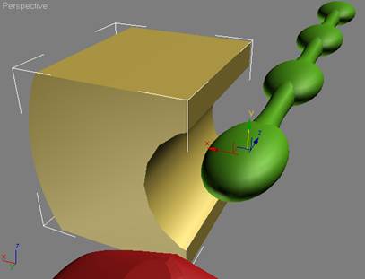
 - Now select the front section, go to Create->Geometry and select Compound Objects from the pull-down menu, and then click on Boolean.
- Make sure that Subtraction (A-B) is ticked on the Parameters rollout, click on Pick Operand B under the Pick Boolean rollout, and then click on the ChamferBox you just created.
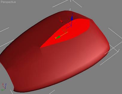
- With the front section still selected, select Cap Holes from the Modifier list rollout on the Modify panel, and you should have something that looks like:
Note: If the Cap Holes modifier doesn't work correctly, then undo it, convert the front section to an Editable Mesh, select the Polygon sub-object, and then use Create to connect the vertices into polygons. - OK, next let's make a quick & dirty bridge, from which we can fly this thing. To do this, we'll simply use slice. With the front section selected, apply the Slice Modifier from the Modifier list on the Modifier panel, and position it something like this:
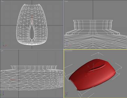
 - Click on Remove Top, apply the Cap Holes modifier, an Edit Poly modifier, and then select the resulting polygon. It should now look like:
 - At this point, you can get a bit creative with simple Extrude and Inset actions from the Edit Polygons rollout. I did a series of Extrudes, Insets, and Uniform Scale operations to create something that looks like:
 - So I now have a mesh with 1,753 polygons that I can use for the front section of my ship. I'll wait to texture it until I get the rest of the hull built.
[edit]
Step 2 – Creating the Hull OK, the first thing I want to do is create the spine that will run the length of the main hull. I build this using simple Standard Primitives off the Create->Geometry menu.
If you look at the sketch I made, you will see that the center of the hull consists of a series of spherical lumps connected by cylinders.
[edit]
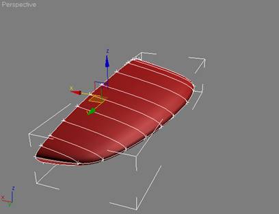
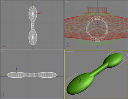
Creating the Spine for the Hull The main shape will be an elongated sphere... so start with basic 32-sided sphere and using the Scale tool, stretch and compress it into a shape you like. Then Shift Drag those using the Transform tool to clone it so you have something like:
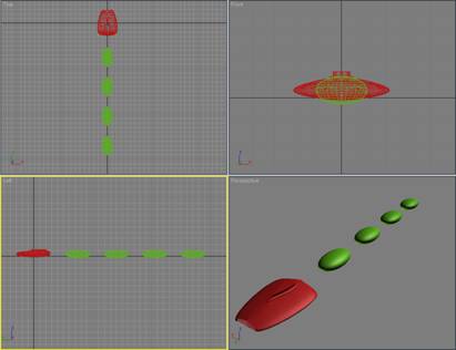
You should take care to space the sphere objects at a uniform distance from each other.
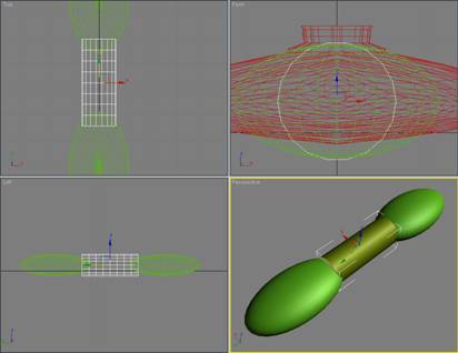
Next, I built the connecting portions by using the Cylinder shape off of the Standard Primitives menu.
I used a cylinder with 18 sides, and 8 height segments. I positioned it so that it is centered on the spheres I just created (e.g. the same values for the x and z axis).
It is not necessary to be precise in sizing the cylinder, since we can always push and pull it into shape as we go along. For simplicity, I made the initial cylinder roughly the same height as the spheres.
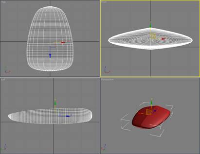
You should now have something like:
I then use the Taper modifier, and Uniform Scale, to reshape the cylinder so that it looks like:
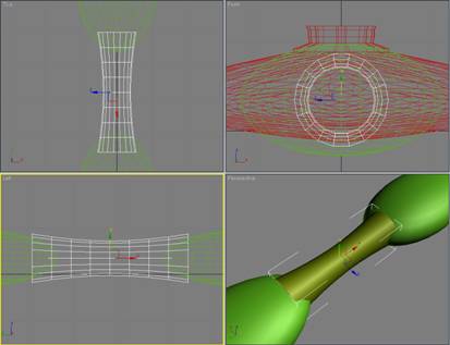
Note that the cylinder is exactly centered between two of the spheres, and that its diameter is now noticeably smaller than the height of the spheres.
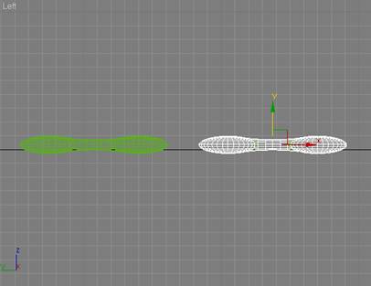
Now again using scale, stretch the cylinder until all the edges are imbedded in the two spheres... like this:
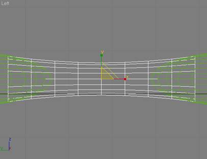
OK, we will need two more of these cylinder objects to join the other spheres. I made two copies, and hid one of them. I then moved the remaining copy down between the last two spheres. Next, select the two spheres that are overlapping the original cylinder and attach them (click on one of the spheres, select Attach from the Edit Geometry rollout, and click on the other sphere).
We could also simply attach the cylinder, but that would leave extra polygons... yech! So, click on Attach again (to turn it off), and then go to the Create->Geometry menu, select Compound Objects from the pull-down menu, and click on Boolean (the combined sphere object should still be selected). On the Parameters rollout, go down to the Operation section and select Union, and then click on Pick Operand B from the Pick Boolean rollout. Click on the cylinder (there are now two of them, but you are only selecting one), and you should have a single object that looks like:
Now we need to join the other two spheres. (Hopefully you remembered to space the spheres at a uniform distance from each other.)
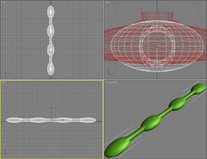
There are two ways to proceed: you can clone/copy the combined sphere object you just built (from the two spheres and the cylinder), move it down to where is should be positioned, and delete the two place holder spheres that are currently there, or you can take the copy of the cylinder which you shifted down between the two separate spheres, and use the Boolean Union operation to join them... which ever you find easiest. Regardless of which way you choose to proceed, you should now have something that looks like:
Now all that is left is to join the two parts of the hull spine into a single object. Take the hidden copy of the cylinder object, position it in the exact center of the hull spine, and use the Boolean Union operation we went through previously to merge everything into a single mesh.
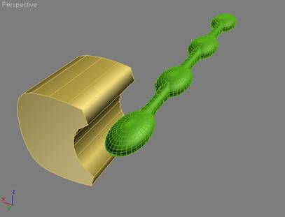
You should now have something that looks like:
Done!
[edit]
Creating the Cargo Pods Now I need to create the cargo pods. Since the ship will be symmetrical, I can work on a single side, and then mirror it to get the completed cargo pod section.
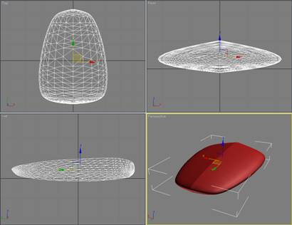
I started with a large cylinder (48 sides, 1 height segment), and centered it on the first lump of the hull-spine. It looked like this:
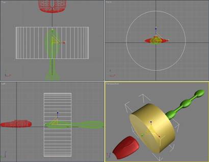
Then, using the Slice Modifier (and Cap Holes), I cut it down to size somewhat... until it looked like this:
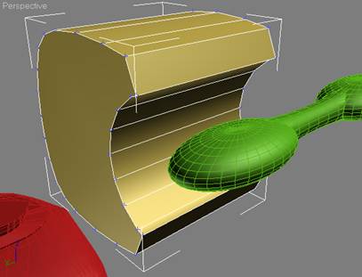
I then created a simple cylinder to use as a cut-out (18 sides), and using the Boolean (Subtract A-B) operation ended up with an object that looks like:
Since I want some curvature on the top and bottom of the cargo pod, I need to add some polygons. There are many ways to do this in 3ds Max, but the approach I took was to use the Edge selection to select one of the top Edges, and then on the Edit Edges rollout, click on Insert Vertex. I then added three vertices on each end of the top, like as shown here:
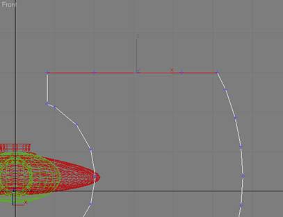
Next, I connect each of the three vertex pairs I just created, and then (working in either the front or back viewport), I select vertex pairs, and move them around to achieve the shape I want for the top of the completed cargo pod It now looks like:
I could create a slightly different appearance to the bottom, but in the interest of simplicity, I'll just use the Slice Modifier to chop off the bottom portion, and then use the Mirror Modifier to create the completed mesh.
Here is what it now looks like:
Note: I removed the extraneous horizontal edge that was left on the ends by the slice/mirror operation.
At this point, just to keep everything nice & tight, I converted the cargo pod to an Editable Mesh, selected all of the vertices, welded everything together (after bumping up the weld threshold slightly), and then converted it back to an Editable Polygon.
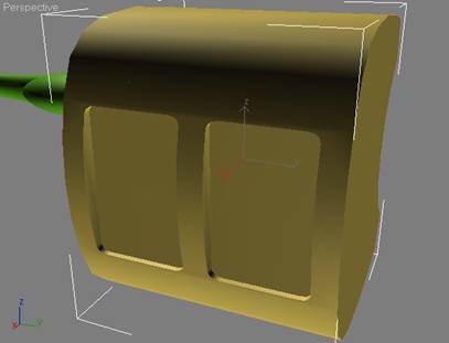
Finally, since a cargo pod should have some way to the wares in and out, I added a hatch cover. I did this by creating a ChamferBox, slicing off one end, and then cloning it so that I had a single object to use as a cutout in a Boolean operation. Here is what it looked like just prior to the Boolean Subtract A-B operation:
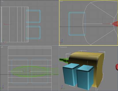
And after the Boolean operation, I had:
OK... the basic cargo pod is done! I then made a clone copy of it that I will use to further develop the remaining elements of the cargo pod.
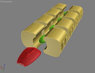
However, before continuing, I like to see what the basic shape of the hull is going to look like, so I can make any adjustments necessary to the cargo pod. To do this, I will clone the cargo pod 3 more times, and position the copies along the spine... in line with the lumps.
In addition to the original, you should now have 5 copies of the cargo pod... the reference copy and 4 individual cargo pod objects aligned down the spine. Attach the 4 individual cargo pods objects, and then after adjusting the x axis for the pivot, use mirror to create a copy on the other side. You should now have something that looks like:
Hmmm... not bad. OK, we've decided that we can live with it, so now it is time to go back and develop the basic cargo pod a bit further.
[edit]
Finishing up the Cargo Pod In order to simplify the final texturing, I have made the hull symmetrical. This way I can work with a single cargo pod, get the mesh fully constructed, apply the texturing I want, and then clone/mirror copy it to build the complete hull.
You can delete (or hide, if you prefer) the combined cargo pods we assembled in the previous step, since we will rebuild it later. For the next few steps, we will only work a single cargo pod, and a cloned copy of one of the lumps from the spine.
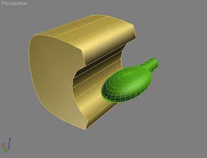
Select the reference copy of the cargo pod and the spine, and Hide Unselected. This is the view you should have in your Perspective viewport:
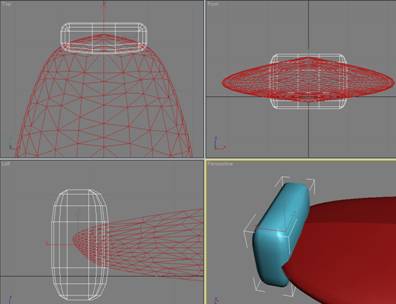
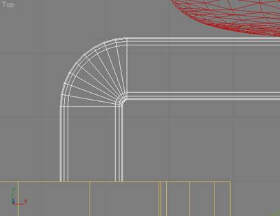
Now we can clone the spine (hiding the original), and then slice off the front lump and half of the first tapered cylinder. I used the Slice, Cap Holes, and Edit Poly modifiers again. The object we are creating is only going to be used ad a reference point, and we will delete once we are finished with the cargo pod. I could have just as easily used the entire hull spine, but my preference is to make copies of things. Anyway, I ended up with the front part of the spine as a reference point... like the following:
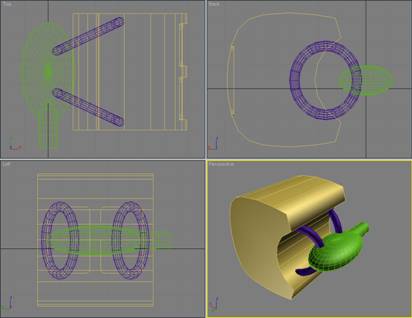
Clearly, the cargo pod needs to be attached in some way to the hull spine. I chose to use a couple of Torus objects from the Standard primitives menu. Here is what they looked like once I positioned them in the scene:
Go ahead and use the Boolean Union operation to merge the two torus objects into the cargo pod.
Now we will place some machinery-like objects and a few connectors between the cargo pods. (Remember, we will be using X3 DDS textures to create the actual image of machinery and pipes.)
[edit]
A bit more inter-pod detail This step is pretty much free form, and is really based on my understanding of what is available in the X3 texture library. There are some pretty nice circular textures, plenty of technical detail, and a few gas tank textures. When I start modeling a ship, I already have decided on the basic texture set I will be using... and that decision has a significant impact on the shape of the objects I use to construct the actual ship.
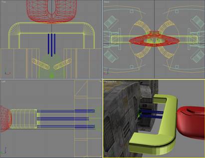
Without going through all the detailed steps used to create the individual objects, here is what I put together for the inter-pod details:
The curved panels on the top and bottom will receive see through DDS textures, as will the rectangular cross-braces. As you can see, the top and bottom are again symmetrical, so I can create the top half, and then mirror it for the bottom.
Using symmetry wherever possible will reduce your workload by up to 50%. Clearly, it helps to plan ahead, and ensure that your ship design will let you take advantage of this capability.
Also, some of you may have noticed that the purple cylindrical object is shaped very much like one of the large tanks on the Teladi TL... that is because I cut of off of that model and put in an a library of shapes that I can reuse.
Our good friends at Egosoft have built some excellent models, and a smart modeler will not hesitate to chop off a few bits here and there and save them for re-use in your own work.
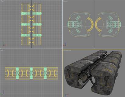
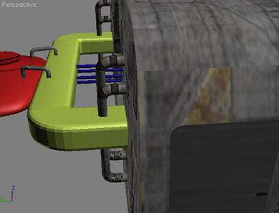
When I built the inter-pod part group, I made sure that it was exactly wide enough to fit between two cargo pods... as can be seen in the following screen shot:
Now for some bad news... this tutorial is not going to tell you how to texture the model... that is a major topic in itself, and is outside the scope of what I am doing here. However, once textured, here is what the inter-pod part grouping looks like in 3ds Max (it looks much better in X3):
There are quite a few excellent tutorials on texturing that come with 3ds Max, and I would encourage you to run through them to become familiar with the basic texturing tools. Also, spend some time going through the Egosoft-supplied texture library. If you know ahead of time that you can use a DDS texture to create the detail effect you are looking for, then you can avoid the need to create unnecessarily complex objects.
OK, we still have a couple of parts to go, but we now have enough to assemble the cargo-pod section of the hull. After texturing the cargo pod we built earlier, we can use clone/mirror operations to create something that looks like:
The next step is to build the parts that attach the front section to the hull spine and cargo pods. This can be fairly simple, since we will again be relying on DDS textures to make things look good in X3.
Since there was no real detailed plan for the ship before I started (other than my back of the envelope sketch), I have to create the attachment object(s) on the fly. However, to keep things in proportion, I need to keep in mind the overall look and shape of the ship so far. If I un-hide everything, this is what I've got:
It seems to me that the simplest solution is to build an arch between the two halves of the hull which passes just behind the front section... and maybe some pipes running back to the spine.
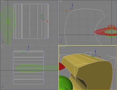
There are many ways you could do this, but I chose to start with a simple ChamferBox:
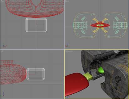
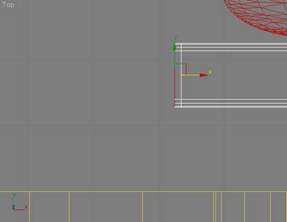
Now I want to extend one side of the ChamferBox, and gradually curve it back to join up with the cargo pods. I only need to work with one side, since once I get it correctly built, I can simply slice the ChamferBox in the middle, and mirror the good half. Accordingly, I simply use Slice/Cap Holes to square off one side of the ChamferBox, and then stretch it out so that it looks like this:
Here is where it starts to get tricky again. I extrude the end slightly. Like:
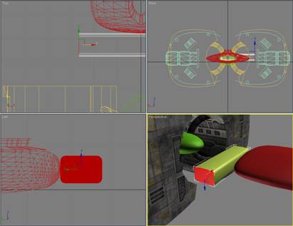
... and then (leaving the polygon on the end selected), Rotate it 10°like this:
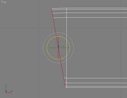
You can see that the bottom of the polygon I just rotated has crept up slightly... so I move it down like:
OK... now you know what needs to be done, and after a series of Extrude, Rotate, and shift down operations, I ended up with this:
After a Slice and Mirror operation on the arch, and the addition of a four narrow cylinders, I had this:
Hmmm... not bad, but it looks a bit plain, eh? Here is where you can really make up time. As I mentioned previously, the folks at Egosoft did some mighty fine modeling, and since I am going to be using their textures... why not grab a few parts off some of their ships to add the missing detail?
Since I am using a number of textures from the Teladi scheme, I'll go and grab some pipes from the Teladi TL.
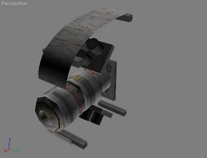
Here we are with the pipes applied... getting better?
Before I texture the hull spine, front section, arch, and connecting pipes, I'll spruce up the front section by adding another part from the Teladi TL... like this:
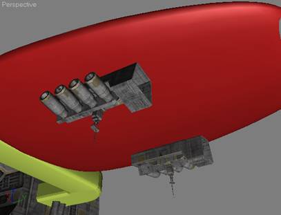
So, next I texture the other parts, and then move on to building the thruster section. (Note, I also added some antennas from the Teladi TL once everything was finished, as can be seen from the screen shots.)
Before we get started on the thrusters, I'll give you a view of the ship as it is currently textured. However, I would also like to point out that once you get a ship into X3, and actually get to see it in various light settings... you will almost certainly find elements that you want to tweak. For me, this most often involves texturing. At the risk of boring you with disclaimers... as I said at the beginning, I'm no artist!
Anyway, here is what I have so far:
Now... on to the thrusters!
[edit]
Step 3 – Building the Thrusters First, decide on the general configuration of the thruster. Unless you are following a specific design, I find it easier to wait until the rest of the ship is done... in hopes that I'll be struck by an inspiration.
For whatever reason (possibly insanity), I decided to go with two main thruster bodies, one for each hull side, and to have three thruster nozzles in each body.
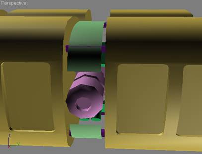
Since I wanted three nozzles, I chose to start with three-sided Gengon object. I could have used a sphere, or even a box object, but I have had good luck with Gengon. (It is in Create->Geometry->Extended Primitives.) Once I had the initial Gengon shape, I used a series of Extrude and Uniform Scale operations to create the basic thruster body. Once I had the right shape for the thruster body, I used three cylinders as my cut-out for a Boolean Subtract A-B operation.
Here is what the Gengon and cut-out looked like before the Boolean operation:
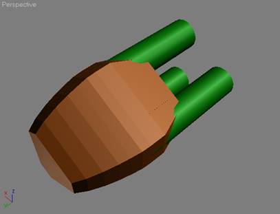
Remember, Boolean operations can be a real pain. You may want to avoid them until you are comfortable working at the vertex level. Unless the A & B objects you are working with are very simple, you will almost certainly need to move, weld, remove, etc a number of vertices in order to get things looking pretty.
So after the Boolean operation (and a little clean-up on the vertices), here is what I ended up with for the completed thruster body:
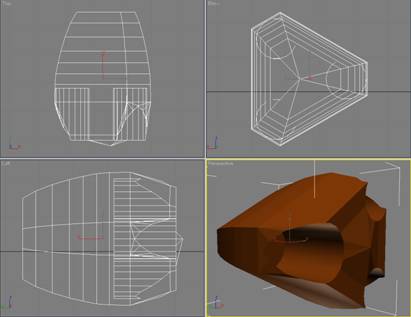
I then applied a smoothing group to the outer polygons to get a more refined shape, like this:
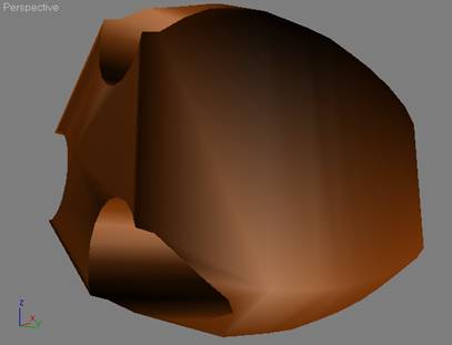
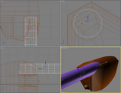
Now to shape the nozzles, I started with a cylinder (18 sides, 10 height segments). It is easy to add height segments as you go along, but since I knew in advance that I would be using quite a few in order to create the ridges and curves that I had in mind, I started with 10.
Before starting in on shaping the nozzle, I made sure that the basic cylinder I was using fit nicely into the holes I had cut in the thruster body. Here is what I had at this point:
... and without going through all the trial & error involved in getting a pleasing shape for the thruster nozzle... here it is:
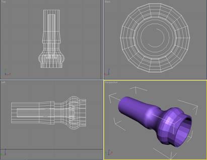
I have employed a fairly complicated internal structure, since I plan to use a number of self-lighting DDS textures. Otherwise, I wouldn't have wasted the polygons.
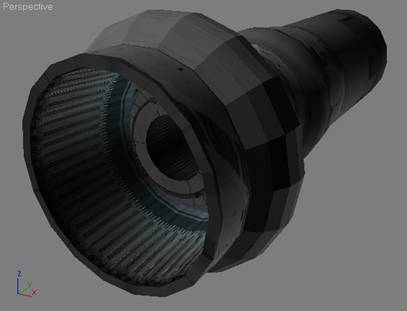
Here is the nozzle after texturing. Remember, you can't really see what it will look like until the X3 rendering engine gets a hold of it in-game.
Then, after hacking some textures onto the thruster body, and cloning two more nozzles, this is what I have in the way of a thruster assembly:
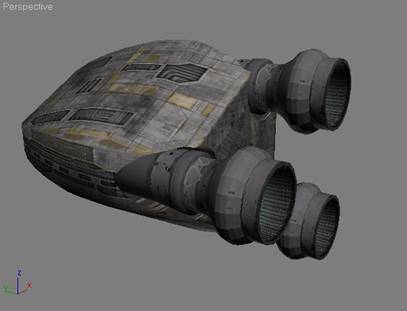
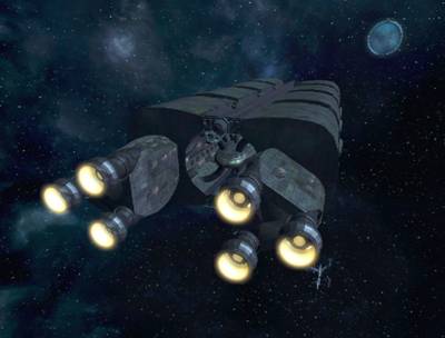
After doing a mirror/copy to get a thruster on the other side, I can un-hide everything and (hopefully) have something that looks pretty much like an X3 TS class ship.
Let's see how close I came:
To be honest, that is pretty much what I was hoping to end up with. Rest assured, that's not always the case!
As I said previously, once you play around with a new ship in-game, you will always find a number of things that can be improved.
No, all we need are a few finishing touches like a cockpit, and a turret, and we are ready to export out new ship into X3!
[edit]
Step 4 – Making it work in X3 At this stage of things, there is a fair bit of personal choice involved. If you are only going to make one or two ships, go ahead and do it in the easiest way possible.
However, if you end up doing very many ships, you will thank yourself if you establish some conventions right up front.
I won't describe my entire development workbench (that's another tutorial in itself!), but you should at least have some idea of how you want to store your work. Within my development environment, I have separate folders for each ship. Within the root folder for a ship, I keep the various versions of the 3ds Max files, as well as the X3 scene file for the ship. In addition, if I am using a unique multi-texture for a given ship, then the text file with the X3 texture definitions is also kept here. In the root folder, there is a sub-folder called /parts. This is where I save the various parts for a ship when I use DBOX to export them.
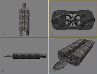
Nothing says that you can't simply lump everything together into a single mesh... Egosoft frequently does. However, I prefer to group the various 3ds Max objects I create when building a ship into 2 or 3 (sometimes more) parts. It's a personal preference thing, and you can do it however you like.
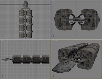
For this ship, I grouped the ship objects into three parts: front, hull, and thrusters. It looks like:
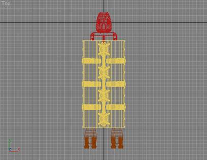
Before we can get going, we will need to make sure the ship is reasonably sized for a TS class ship. I do this by selecting and grouping all the parts of my ship, and then importing (using DBOX) an existing X3 ship that I know is the right size:
Here I have imported a large Paranid TS, and you can see that my model is too small!
Since I've already grouped the parts for my ship, I can use Uniform Scale to adjust the size.
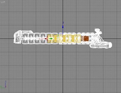
Checking from the top viewport, things now look a bit better:
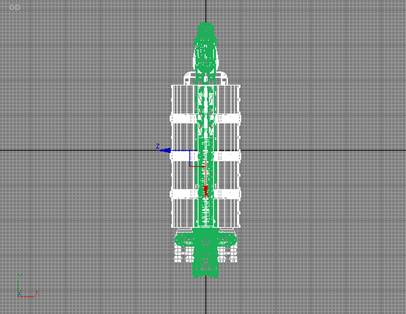
So I delete the Paranid model, and get ready to start exporting my ship. However, before I start, I need to add in a couple of special X3 objects, to complete the ship.
Using doubleshadow's DBOX tool I imported:
- A copy of the Egosoft-supplied cameradummy.bod file from the unpacked X3 folder called objects\ships\props.
- A copy of my custom d_turret_b91_dummy.bod file (a dual-laser turret).
- A copy of the fx_engine_emitter.bod file from the unpacked X3 folder called objects\effects\engines.
The first step is to place the cameradummy.bod object just over and in front of where I want the viewpoint for the main cockpit to be. (There is another way of doing this, using an updated Components file... but I'll keep it simple for now.)
Here is a view of where I positioned the cameradummy part:
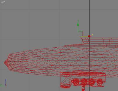
Next, you must rename the cameradummy part to ships\props\cameradummy_1. This is essential, since without the ship\props\ path information, X3 will not find the part, and without the _1 suffix, X3 won't know that this is your main cockpit viewpoint.
The second step is to position the turret. I rotated it 180°, and placed it on the top portion of the aft cross-brace.
Once positioned, it looks like:
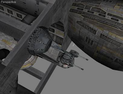
We also need to rename this part to ships\props\d_turret_B91_dummy_2. I always follow the Egosoft convention of keeping general use ship parts in the ships\props folder. The _2 suffix tells X3 that this turret will be fired from the #2 cockpit... which we'll add now.
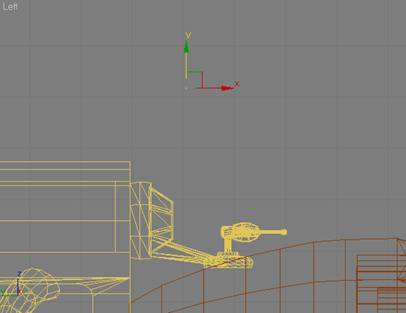
Rather than importing another copy of cameradummy, I simply clone the one I already have, and rotate & position it as appropriate. (Remember, the turret has been rotated 180° so that it will be facing aft, so we need to rotate the camerdummy part in the same way.) This time, we rename the camerdummy part to ships\props\cameradummy_2, to let X3 know that it is the #2 cockpit.
I like to position the cockpit view above the turret, to get maximum visibility. Here is what I ended up with:
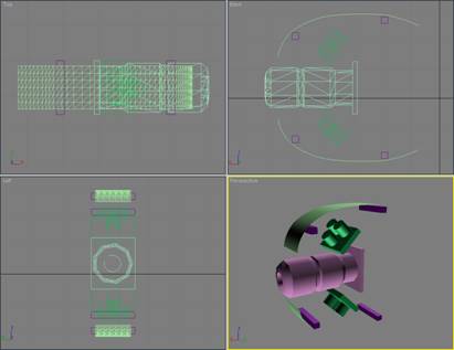
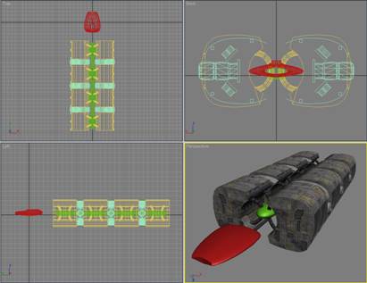
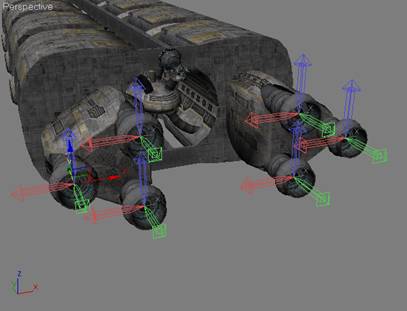
The final (and optional parts) that I will use is the fx_engine_emitter. To use this part, it must be rotated 180° (looking from the top), so that it faces aft. You will also need to rename the part to effects\engines\fx_engine_emitter so that X3 can find it. I clone it 5 times (so that I have six of them... all with the same name), and place them in the center of each thruster nozzle.
In the following screenshot, I have selected all six of them and then clicked on Pivot, so that you can see their position and orientation:
在最后能开始输出scene文件的步骤前, 需要重新命名船的各部份。 正如用cameradummy部份的情形, X3需要知道我们把船体文件放的地方,以便渲染. 譬如我,船体文件放在了ships\Deadly\TP-Mk3\parts中,而scene文件放在了ships\Deadly\TP-Mk3中.
因此我重新命名如下:
front 到ships\Deadly\TP-Mk3\parts\front
hull 到ships\Deadly\TP-Mk3\parts\hulll
thrusters 到ships\Deadly\TP-Mk3\parts\thrusters
接下来就是用DBOX进行输出(export):
选择船体部分, 确定模型中心在3DsMax的正中央, (层次Hierarchy->中心pivot, 然后按下生效Affect Pivot)
从工具Utilities菜单,选择重新设定XForm, 然后按下重新设定。
从工具Utilities菜单,选择塌陷Collapse, 然后按下塌陷。
小心地记住(有必要就写下来) 船体模型的x,y,z坐标。
设定x,y,z坐标到0,0,0.
在DBOX面板, Exporter设置中,确定File type选择的是body, 然后按下Export Sel按钮。
注意:要求输入文件名的时候只要名字,不要输入路径,例如ships\ deadly\TP-Mk3\parts\front,文件名就保存为front。
重设x,y,z坐标原始值。
当你把所有船体模型输出后,该为船输出scene文件啦。 为了输出scene文件, 请选择所有的部份 (包括cameradummy/turret/engine effects等),再一次去DBOX的Exporter设置, 这次确定File type选择的是scene, 然后按下Export Sel按钮。 我把这个scene文件保存在上一级的文件夹里。
现在scene和船体模型可以被装载了, 然而,贴图还是不行,因为他们以本文的格式被保存的。
修改从DBOX输出的文件在Egosoft论坛上的某处我有帖子how to use X3 textures了。
DBOX输出.BOD格式的文件,这意谓着他们可以被任何本文编辑器(例如Windows的“记事本”)编辑。
现在, 假设我导入了一艘Teladi飞船(TL)并且抓取了它的材质贴图用在我的模型上。 (我是不用的, 因为我有自己建好的材质贴图库....)
注意: 在Egosoft论坛的Scripts&Modding Forum,我有关于X3 Texturing的帖子。
诺,就是这个:
翻译在原文下面 By HammerSun
I've been asked several times how to apply X3 textures to custom ships...and I know I've written this at least three times and sent it to people, but I just can't seem to find it.
Since I've just been asked again, I'll do what I should have done at first, and post it here in the forum.
Before I continue...let me make it very clear...caveat emptor! There may be easier ways of doing this, and subsequent versions of DBOX (or the release of the X3 Modder Kit) may eliminate the need for the following steps. What I describe below works for me...every time. If you find an easier way, please post it so everyone can benefit.
OK...the first thing I had to do was create a "template" of the textures I wanted to use. By template, I mean an existing MAT6 multi-texture I could apply to my own meshes. The way I went about this was to select a ship already in X3 which had a set of textures I wanted to use. Most of my ships use the base texture set that is associated with the Argon M2, since it looks pretty good and has a fairly large number ( 48 ) of DDS textures to choose from.
So...you have picked a ship which uses the texture set you would like to apply to your own mesh(s). Now you must: 1. Use Doubleshadow's X2BC to de-compile the BOB file for your selected ship into a BOD file, and then import it into 3dMax using the DBOX tool. 3. You then save the multi-texture associated with the BOD file you just imported to the 3dMax texture library so it can be used later on your won meshes. 4. Once the X3 multi-texture is saved, you must open the original X3 BOD file you used to get the multi-texture in a text editor. In the text editor, select the MAT6 entries at the begriming of the file then save them as a text file (it should only contain the MAT6 entries). (The Argon M2 multi-texture that I often use has 48 MAT6 entries.) The resulting text file is what I call the "template", and it should be an exact match of the multi-texture you saved earlier. 4. Then, when in 3dMax, you can load the X3 multi-texture you saved, and apply it to whatever mesh you wish. 5. Once the mesh textured to your satisfaction, export it using DBOX (always remember to keep Data Handling and Comparability set to X3). If you were to look at the MAT6 entries in the BOD file you just exported using a text editor, and compare them to the MAT6 entries in the X3 BOD file for the ship you selected, you would see that they are "broken". 6. So, the final step is to correct the MAT6 entries in your exported mesh by opening the BOD file in a text editor, as well as opening the "template" you had previously saved, and then using the copy & paste functions to replace the "bad" MAT6 entries in your exported BOD file with the "good" MAT6 entries from your template.
You now have your mesh in BOD format, with X3 textures applied.
Use X2BC to compile it back into a BOB file...and you're good to go
It is quite easy to add X3 DDS texture entries to extend your template(s) using the same principals described above.
已经有N多人问我如何制作X3的材质贴图,而且我写这个内容的帖子已经不下三次了, 但是我找不到以前写的了。
自从我又不断被问后,我将做我应该做的, 而且在论坛中发贴呀。
在继续之前。。。让我申明一下。。。货物售出,概不退换!
在DBOX有了更新的版本或(X3 Modder Kit)出现后,可能有更容易的方法来做下面的事,或者干脆不需要做了。
Okay。。。第一件事是做一个我想要使用的材质贴图"模板template"。 这个模板template,我指的是MAT6 multi-texture。 我处理的方法是 在X3中选择一艘有我想要的材质贴图的飞船。 我大部分的船使用了Argon M2相关贴图,因为它看起来漂亮,行而量也很多呀(48个.DDS文件)。
接下来。。。你已经挑选好你想要的材质地组的船了,现在你要做的是:
1. 用Doubleshadow's X2BC把你所选船的.BOB文件转为.BOD文件,再用DBOX把它导入到3dMax中。
2. <原文中就没有的... HammerSun注>
3. 保存刚刚导入文件的材质贴图到3dMax的贴图库。
4. 保存好后,必须要打开X3原始BOD文件<用文本编辑器>。 在本文编辑器中, 选择有MAT6的条目,把它们另存为文档.(应该只包含MAT6条目entries)。 (我常使用的Argon M2有48个MAT6条目) 这个文档就是我所称的"模板template" ,而且它应该是精确匹配步骤3中保存的材质贴图的。
4. 然后, 在3dMax中,装载步骤3中保存的材质贴图文件, 应用到你想要的过得相关数据)。如果你再察看BOD文件中的MAT6条目, 你会发现他们被坏掉了.
6. 因此, 最后的步骤是用文本编辑器打开你导出的BOD文件,纠正破坏的MAT6条目。 打开你先前保存的的"模板template", 然后粘贴到复制到坏的MAT6条目中。
现在,你的飞船模型能够被X3正确贴图了。
用X2BC把BOD文件编译回BOB文件。。。好啦。
Since we are exporting data from our 3ds Max scene into a proprietary format, and Egosoft has not yet published an X3 Modders Kit (as they did for X2), there is some information in the output produced by DBOX that occasionally needs to be modified.
Please note that this is only true for the ship I built in this tutorial because I chose to use the new big MATERIAL6 textures... which not only use the new DDS textures, but also employ the special graphic shaders as well. If I had chosen to use standard X3 textures, the output from DBOX could be used directly in the game.
That said, there are a number of steps required to get your ship flying around in the X3 universe:
- Updating the MATERIAL6 texture information:
- If you look at the part files exported by DBOX in a text editor, you will see a number of lines at the front of the file starting with the word MATERIAL6. Each of these lines describes an X3 texture.
- If you then look at the stock Teladi ship used to grab the textures for your ship and compare the MATERAL6 entries, you will see that they are different. So... the MATERIAL6 entries need to be the same.
- The easiest way to do this is to simply fire up your favorite text editor, and copy the good entries from the Egosoft BOD file over the top of the bad entries in the BOD files for the custom parts for your ship.
- Now that you have the correct MATERIAL6 information in your BOD file, you could use it as is in X3, and it would load correctly... if a bit (maybe a lot) slow. There is a reason the Egosoft's ships are provided in BOB (actually, compressed as PBB files, but lets not confuse things any more than necessary). X2BC (the same tool you would have used to convert the Teladi BOB file into a BOD file) can also be used to compile the edited BOD files (with corrected MATERIAL6 data) into BOB files.
Whoa... what could be easier, eh?
That's it! You're done! Simply fire up your trusty copy of X3 Editor and add the necessary entries to the TShips file, and then use X3 ModManager to package it into a mod.
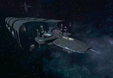
... and you will be looking at this in X3:
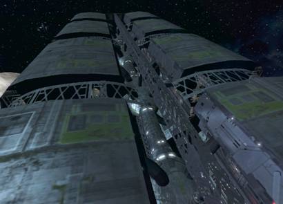
Looking down the spine...
Here is a view of the core of the hull, showing some of the detail on the spine...
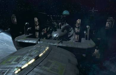
... and finally, a view from the aft quarter, looking forward:
I know I have covered a huge amount of ground, and trying to pack all the necessary information into a single tutorial is sort of like forcing some one to take a drink from a fire hose, when all they really wanted was a sip of water. However, it was the best I could do (and much more work than I had planed).
Hopefully some of you will find the information useful in your own modding efforts.
Enjoy!
[ 本帖最后由 HammerSun 于 2007-5-1 02:41 编辑 ] |
评分
-
查看全部评分
|
 /1
/1 


 狗仔卡
狗仔卡 发表于 2007-4-27 18:05:53


 提升卡
提升卡 置顶卡
置顶卡 沉默卡
沉默卡 喧嚣卡
喧嚣卡 变色卡
变色卡 抢沙发
抢沙发 千斤顶
千斤顶 显身卡
显身卡 发表于 2007-4-28 15:37:46
 发表于 2007-4-30 22:02:20